


TopSolid’Mold: control mould-based tool design from A to Z
The plastic moulding industry is becoming more complex every year. Manufacturers of moulded parts now have a whole series of constraints to contend with: highly sophisticated geometries, multiple functions and very tight deadlines, to name a few. That increasing...

TopSolid’Inspection: automated quality inspections you can trust
With production lines under serious pressure, in a context marked by increasingly strict regulatory traceability requirements, quality inspection has a key role to play. Not least because every part has to satisfy ever more stringent standards, and the slightest...
Mecachrome secures its workshop flows with TopSolid’ShopFloor
Discover how Mecachrome has improved the reliability of its CNC transfers and enhanced workshop traceability thanks to TopSolid’ShopFloor at its Montauban site.

TopSolid’ShopFloor: Reinventing Workshop and Tool Management
Managing tools, programs, and production workflows is a daily challenge for modern workshops—and for good reason. These essential tasks are often time-consuming, error-prone, and fragmented across systems. But what if a fully integrated solution could turn the tide? Discover five key innovations in TopSolid’ShopFloor designed to drive faster, more reliable production.

TopSolid’Predict: Unlocking the Power of AI-Enhanced CAD
TopSolid’Predict revolutionizes CAD by integrating artificial intelligence and augmented reality. Discover how these technologies are transforming digital design and optimizing industrial processes
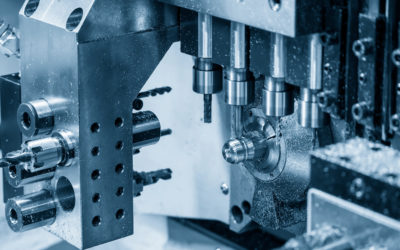
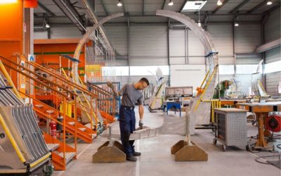
The Swiss Turn Revolution: Advanced Precision, Innovation and Machining Solutions
Swiss Turn refers to a technique for machining very small parts with an extremely high degree of precision, up to a thousandth of a millimetre. Originally developed for the watchmaking industry, the technique has evolved and adapted to the precision and productivity requirements of other industries.
![[CASE STUDY] Project management in the civil engineering industry: Arden Equipment’s transition to an integrated TopSolid PDM/CAD/CAM solution](https://blog.topsolid.com/wp-content/uploads/2023/02/AE-COUV--400x250.png)
[CASE STUDY] Project management in the civil engineering industry: Arden Equipment’s transition to an integrated TopSolid PDM/CAD/CAM solution
Specializing in the design, the manufacturing, and the distribution of tools for public works machinery, Arden Equipment leads the market with its full range of tools. Two essential factors drive the company’s activity: the constant monitoring of innovation in its sector by a very active Design Office and the desire to ensure continuous interaction between its teams and their customers.
![Collaborative design, data traceability, virtual reality… Learn how digital engineering is revolutionising the industry and stay one step ahead of your competitors! [WHITE PAPER]](https://blog.topsolid.com/wp-content/uploads/2023/10/livre-blanc-ingenierie-digitale-400x250.jpeg)
Collaborative design, data traceability, virtual reality… Learn how digital engineering is revolutionising the industry and stay one step ahead of your competitors! [WHITE PAPER]
Do you want to improve flexibility, quality and operational efficiency while cutting costs? That’s what digital engineering for Industry 4.0 is promising.
Digital engineering is booming and appears to be the obvious answer for design offices and R&D departments keen to digitalise their practices and reduce their environmental impact. Collaborative design, 3D modelling, virtual and augmented reality, data traceability… A design and production method that uses digital tools to improve the efficiency and precision of industrial processes, digital engineering encompasses a wide range of technologies.
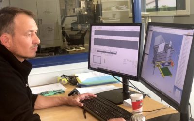
Discover how TopSolid’ShopFloor revolutionises the manufacturing process of your components
In a world as demanding as industry, efficient workshop management is essential to remain competitive. This is where TopSolid’ShopFloor stands out. From the first 3D import to the machined part, this integrated software offers a complete solution to streamline your manufacturing processes. Automated import, tool creation and management, NC program and loading, tool stock management… TopSolid’ShopFloor proves to be an invaluable ally throughout the chain. Ready to optimise your operations with TopSolid’ShopFloor? Find out how this integrated workshop management software is set to change your life!

How collaborative design and digital engineering are revolutionizing the work of design offices?
Imagine a symphonic orchestra made up of engineers, CAD technicians, architects and industrial draftsmen. In recent years, collaborative Computer-Aided Design (CAD) and software engineering have evolved significantly and new, more modern instruments have been developed that offer new possibilities and a new collective dynamic. Just like an orchestra that tunes up to play beautiful music together, design offices are harnessing these different digital technologies to achieve excellence in their projects.

CAD: all you need to know about computer-aided design
CAD software, which is used to digitally model parts or machines, is indispensable in numerous sectors of activity. As well as making technical improvements, it also forms a link between different fields of expertise and helps to improve the complete design process. We take a look at this tool, its applications and its benefits for enterprises.

How is the digital transition shaking up industry?
Adapting to these new technologies is not just a matter of survival, but also an unavoidable factor of competitive performance. Do you have any doubts? Do you have trouble realizing to what extent your company is involved in this transition? You cannot really measure the risks or what is at stake? Are you are wondering whether this is simply a nebulous concept? Let us explain everything.

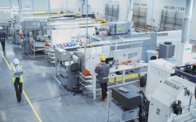
Your complete guide to machining
Machining plays an essential role in the production of high-quality precision parts. Whether you are an engineering professional or just curious, and want to learn more about this industrial technique, then this complete guide to machining is perfect for you.

How 3D design and digital engineering can optimize progress reports
In industry, the regular production of these documents can take a long time and often produces fruitless or unusable results. But, thanks to 3D design and digital engineering, it is possible to quickly produce comprehensible documents and efficient views that provide customers with a clear vision of the state of progress of the project.

Why should SMEs consider tailor made configuration?
Custom configuration meets both the consumer’s desire for personalization with the company’s economic viability. Explanations.

CAD/CAM for grinding on your machine tools
More precise than traditional machining operations, grinding enables the surface of a product to be finely modified thanks to the abrasive machining technique. Nevertheless, investing in the right machine tools to perform this type of operation represents a significant cost for companies, more so as their piloting can prove difficult for programmers. To facilitate grinding on these machine tools, some manufacturers are exploring the possibilities offered by CAD/CAM. But what additional advantages does CAD/CAM offer this activity? Here’s how.
Success Story: TopSolid by Rabumeca
Based in the Ain region of France, Rabumeca designs and manufactures welded assemblies in steel, stainless steel, and aluminum for various sectors. Founded in 1989, the company boasts many years of experience in its field, which earned it the “quality, cost, delivery” award from ArcelorMittal in 2013. Since 2020, Rabumeca has been integrating TopSolid’Design software into its design process—interview with Sébastien Bridet, Rabumeca’s Managing Director.
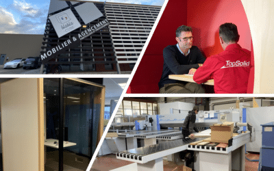
Success Story: TopSolid by Structa
Structa is a 6500 square-foot workshop situated in the heart of the Drôme region, specializing in custom-made furnishings. Since 1981, the company has dedicated its expertise to designing and manufacturing furniture tailored to its customers’ needs. In 2006, they integrated TopSolid’Wood software into its design process to optimize it.
In this interview, we talk with Christian Salomon, CEO of Structa, whom TOPSOLID proudly supports in his projects.
Métallerie Serrurerie Kopko: the customized parts expert who trust TopSolid’Steel
Founded in 2017 in Reims, Métallerie Serrurerie Kopko, also known as MSK, deploys its know-how and expertise in creating custom metal structures. Glass roofs, staircases, gates, metal doors and joinery, made-to-measure furniture, glass floors, and ceilings… MSK aims to enhance various spaces with distinctive elements, whether it’s an entrance hall, walkway, or contemporary furniture. From feasibility studies to 3D design and manufacturing, MSK relies on TopSolid’Steel to comprehensively fulfill its customers’ requirements. Let’s focus on this successful collaboration.
![Mechanical engineering: making a successful digital transition today to better meet tomorrow’s productivity objectives [WHITE PAPER]](https://blog.topsolid.com/wp-content/uploads/2022/07/LB-Industrie-Mecanique-Blog-400x250.jpeg)
Mechanical engineering: making a successful digital transition today to better meet tomorrow’s productivity objectives [WHITE PAPER]
Industry 4.0, through the digital transition and the adoption of new technologies, is the main challenge for mechanical industries. Robotization, implementation of management systems, simulation, digital twins, production management, workshop management, Cloud...