Mecachrome secures its workshop flows with TopSolid’ShopFloor
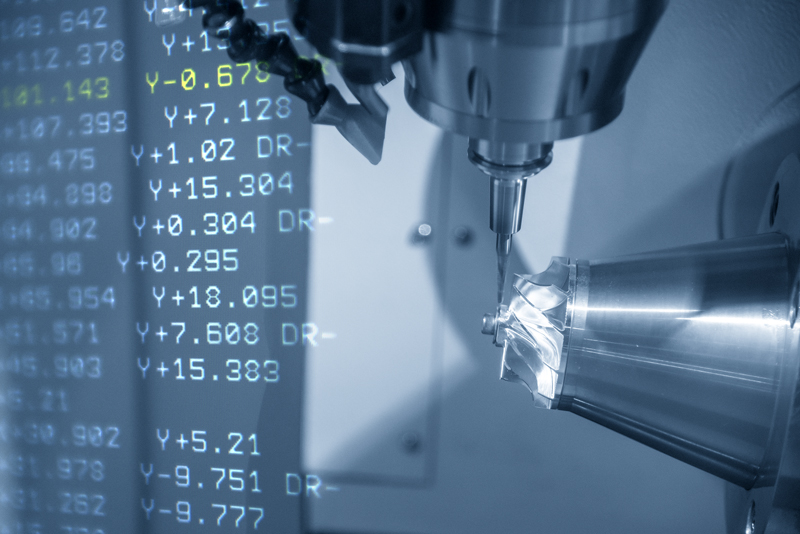
©Mecachrome
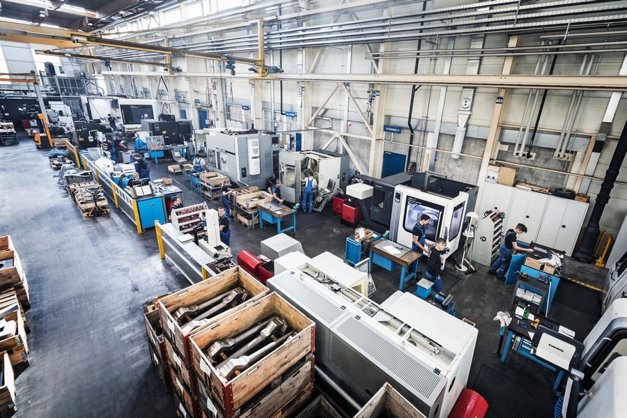
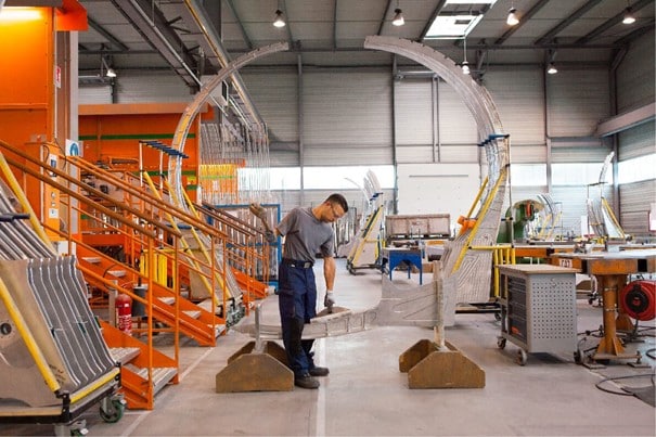
With over 80 years’ experience in high-precision manufacturing, the Mecachrome group has taken its digital transformation to the next level. At its Montauban site in southwest France, integrating TopSolid’ShopFloor has secured NC transfers and significantly improved the traceability of operations. We take a look back at a high added-value project.
A challenging industrial context
The Mecachrome site in Montauban, which specialises in complex turning, is a key player for customers including Airbus, Safran and Thales. Working in build-to-print mode, it combines technical expertise and extremely demanding quality requirements. However, despite the site’s top-level functional expertise, the NC program transfer methods had some weak spots.
Before the project, files were sent via a wifi network, and signal losses, incomplete transfers and doubts about which version was being used were commonplace. Those contingencies had become unacceptable in such a critical environment.
A targeted solution with TopSolid’ShopFloor
As part of its policy of structuring workshop flows, Mecachrome opted for the TopSolid’ShopFloor solution, and more specifically, the Program Manager module. The aim was to secure NC transfers, improve traceability and centralise file management.
“We were looking for a simple, secure solution that would fit seamlessly into our TopSolid environment.”
— Thibaud Luvisutto, Industrialisation Manager
The group selected a tool native to the TopSolid’Cam environment, capable of managing machine-specific access rights, time-stamping every action and tracking all users.
A speedy roll-out, a cultural shift
From a technical standpoint, the project was rolled out in record time: software installation, wiring of the machines, entering of the profile settings, training and so on. It only took a few days to get the system up and running.
However, in terms of use and practices, the change was more significant. For operators, it meant switching from an informal software program to a structured process involving validations and checks. They needed time to get used to the new framework. However, the benefits quickly became apparent.
“It’s a more rigid process, but it’s easy to see the benefits in terms of traceability.”
— Sébastien, NC programmer
Concrete results day after day
NC programs are now centralised and secured, and every transfer is clearly identified. As a result, there are fewer errors, teams are reassured, and it is much easier to analyse incidents and learn from them.
“We now have a real overview of the files sent. We can identify the origin of any anomaly.” — Sébastien, NC programmer
This first step paves the way for more far-reaching digitisation. Mecachrome already plans to explore other modules, such as tool supervision and workshop management.
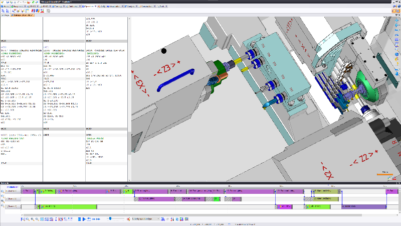
The range of CAD, CAM, ERP and PDM TopSolid solutions


Making the shift to a smart workshop
The Montauban site has achieved a strategic milestone by adopting TopSolid’ShopFloor. This project embodies a modern vision of the workshop: smarter, more structured, yet fully geared to operational performance.
“We can clearly see the potential to go further, without creating any extra work for our teams.” — Thibaud Luvisutto, Industrialisation Manager
You may also enjoy: Discover the new features in the 2025 version of TopSolid’ShopFloor
Want to know more about TopSolid’ShopFloor and its workshop applications?
Try out the free version and/or request a demo now.