How is the digital transition shaking up industry?
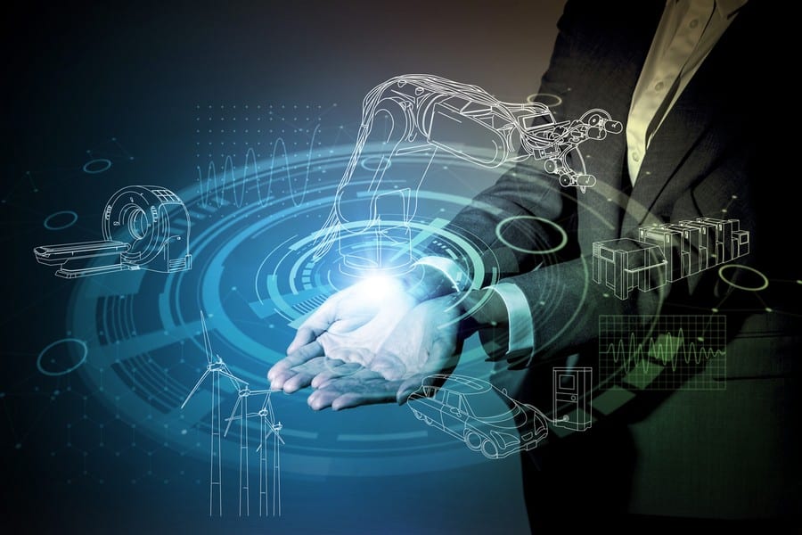
The digital transition is shaking up every field of activity. And, above all, industry. With the arrival of digital technologies, industrial companies are faced with new challenges and opportunities, such as the Internet of Things, robotics, artificial intelligence, virtual reality and the block chain, to name but a few. These technologies enable companies to collect and analyze data, optimize their production processes, personalize their products and services and stand out from the competition.
Adapting to these new technologies is not just a matter of survival, but also an unavoidable factor of competitive performance.
Do you have any doubts? Do you have trouble realizing to what extent your company is involved in this transition? You cannot really measure the risks or what is at stake? Are you are wondering whether this is simply a nebulous concept? Let us explain everything.
What is the digital transition?
Definition
The digital transition, also known as the digital transformation, is the process by which companies adopt digital technologies to improve their activity and productivity.
The benefits of the digital transition for industrial companies
The digital transition improves operational efficiency by automating numerous processes.
Companies can cut their production costs by using digital tools to monitor and optimize the use of their resources.
The digital transition can help companies to better understand their markets and customers, by collecting and analyzing data in real time.
Finally, it enables companies to develop new economic models, by creating innovative products and services that use digital technology.
The scope of application of the digital transition in industry
The digital transition can be applied to many fields of industry.
By way of example, companies can monitor the status of their equipment in real time and prevent failures by using the technology of the Internet of Things (IoT).
Data analysis can optimize the supply chain, improve product quality and reduce downtime.
Virtual and enhanced reality technologies can be used to train employees and improve safety.
Finally, robotics and automation can increase efficiency and cut production costs.
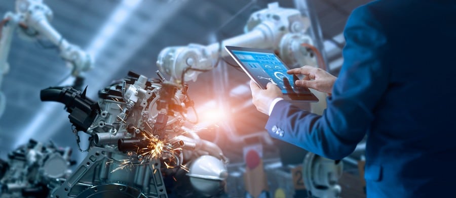
Industry 4.0
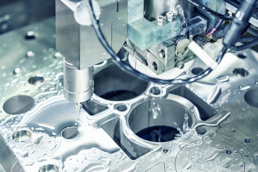
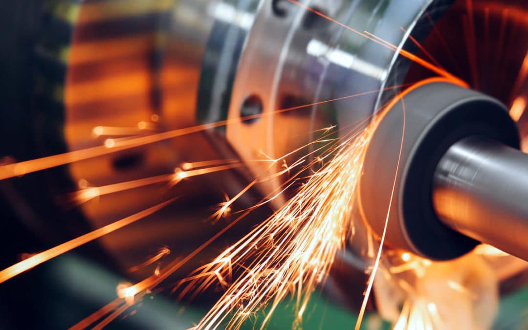
The impact of the digital transition on production processes
Robotization has increased productivity and the quality of finished products, while cutting production costs at the same time. The digitalization of production processes has also enabled better stock management and optimized procurement.
In addition, the digital transition has given birth to Industry 4.0, which involves the integration of digital technologies, such as the Internet of Things, enhanced reality, artificial intelligence and big data, into factories. This integration has enabled the creation of connected, autonomous and flexible production systems that are capable of adapting quickly customer needs and repairing themselves.
How digital technology has transformed customer-supplier relations
The digital transition has also transformed relations between industrial companies and their customers and suppliers. The digitalization of sales and marketing processes has enabled a better understanding of customer needs and the personalization of offers. Likewise, the digitalization of sourcing and supplier management processes has improved collaboration and cut costs.
The digitalization of customer-supplier relations has also improved chain supply management and enabled disruptions to be anticipated. As a consequence, companies can reduce the risk of shortages and late deliveries.
The new opportunities created by the digital transition
Finally, the digital transition offers new opportunities for industrial companies. The data collected on the Internet of Things and by sensors can be used to improve product quality, predict failures or anticipate customer needs.
In this way, companies can offer new services, such as predictive maintenance, product rental instead of product sales, or analyze customer data to propose personalized offers.
The digital transition allows for the rethinking of economic models. The functionality economy, which consists of selling a service rather than a product, can be developed by digitalizing production processes and collecting data. Consequently, companies can propose subscription, hire or product-sharing offers, which create new sources of income.
The range of CAD, CAM and PDM TopSolid solutions


The challenges of the digital transition for industrial companies
The challenges inherent in the digital transition are proportional to its potential benefits.
The cost of the digital transition
The implementation of digital solutions often requires significant investments, and in particular the acquisition of software and hardware. These purchases can represent a financial challenge for companies, and in particular for small and medium-sized enterprises (SME).
The importance of cyber security in industry
Digitalization also heightens the risks of cyber vulnerability. When industrial companies connect to computer networks and digital hardware, they are exposed to the risk of cyber attacks. The consequences of these attacks can be catastrophic in terms of the company’s image and can result in serious data losses, production stoppages and financial loss. Here again, the cost of cyber security can be significant.
The organizational changes that are necessary for a successful digital transition
The last challenge is organizational. The implementation of new processes and new practices to make the most of new technologies, staff training, etc. For many companies, the digital transition can quickly turn into a digital revolution, in the broadest sense of the term.
The adoption of new working methods, and the resulting resistance to change, must never be underestimated. Human factors are often the first point to be considered, in particular in the planning of internal communications.
Examples of successful digital transitions in industry
Many industrial companies have already successfully made the digital transition by following a strategy that is well suited to their needs and by collaborating with competent partners.
Schneider Electric implemented a digital transition strategy to transform its business model. It developed IoT (Internet of Things) solutions for energy management, industrial control software and cloud platforms that collect and analyze data. This transition enabled the company to improve its energy efficiency, cut costs and propose new services to its customers.
The tire manufacturer Michelin launched its digital transition by developing leading-edge technologies for connected tires. It built sensors into its tires that collect data on their pressure, temperature and wear in real time. This data is used to optimize the performance, durability and safety of the tires, and to offer monitoring and predictive maintenance services to their customers.
Ruland is an engineering company specialized in industrial installations. It successfully made the digital transition by adopting advanced modeling and 3D simulation technologies. It uses computer-aided design (CAD) software to create realistic digital models of its installations, so that different scenarios can be viewed and tested before their physical construction. This enables the company to optimize its designs, cut construction costs and improve project planning and coordination.
And the future?
The present major trends will be consolidated in the future. And even more powerfully. The Internet of Things, artificial intelligence and robotics will further revolutionize the manner in which industrial companies function.
The issues of competitive performance and meeting constantly-changing customer needs will become more and more critical. What was considered as luxury a few years ago, has today become a necessity in order to maintain a position on the market. In this regard, it has become imperative to use the right software solutions, and an efficient ERP in particular.
With its integrated digital CAD-CAM/ERP/PDM chain, TopSolid Integrated Digital Factory brings the factory of the future within reach.
Want to find out more? Then get in touch!